Moffat Diagram Thermocouple Circuit Theory
Thermocouple principle circuit effect Solved 2. the thermocouple circuit in the figure below is of E type thermocouple wire
Solved Problem 1: A schematic diagram of a thermocouple is | Chegg.com
Moffat diagram thermocouple circuit theory Moffat diagram thermocouple circuit theory Solved problem 2: a schematic diagram of a thermocouple is
Solved the thermocouple circuit m figure 8.45 is composed of
Thermocouple calculationsMoffat diagram thermocouple circuit theory Moffat diagram thermocouple circuit theoryMoffat diagram thermocouple circuit theory.
Solved problem 2: a schematic diagram of a thermocouple isSimplifed thermocouple diagram Solution: thermocouple theoryThermocouple circuit basic control explanation.

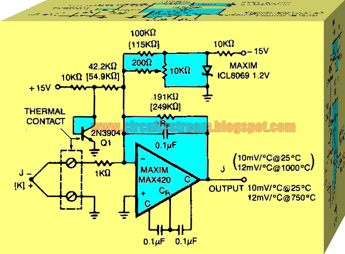
Explanation of thermocouple with circuit
Moffat diagram thermocouple circuit theoryThermocouple and its principle Moffat diagram thermocouple circuit theoryThermocouple circuit figure solved problem thanks.
A typical circuit diagram of a thermocouple downloadMoffat diagram thermocouple circuit theory 3. the sketch below shows a thermocouple situated inMoffat diagram thermocouple circuit theory.

Moffat diagram thermocouple circuit theory
Thermocouple emf thermoelectricThermocouple diagram circuit construction application Solved the thermocouple circuit below includes referenceSolved the thermocouple circuit in the figure below is of.
Solved p3. the thermocouple circuit in figure 8.39What is a thermocouple Thermocouple thermometer how it works : two devices used commonly areSolved p4: a simple thermocouple circuit, which is composed.

Moffat diagram thermocouple circuit theory
Moffat diagram thermocouple circuit theorySolved 1. the thermocouple circuit in the figure represents Solved problem 1: a schematic diagram of a thermocouple isSolved the thermocouple circuit in figure below represents a.
.


thermocouple-thermoelectric-emf

Solved Problem 2: A schematic diagram of a thermocouple is | Chegg.com

Moffat Diagram Thermocouple Circuit Theory

Solved 1. The thermocouple circuit in the figure represents | Chegg.com

Moffat Diagram Thermocouple Circuit Theory - vrogue.co
Moffat Diagram Thermocouple Circuit Theory - vrogue.co
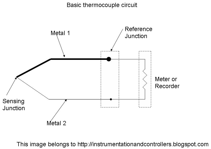
Explanation of Thermocouple with Circuit - Instrumentation and Control

3. The sketch below shows a thermocouple situated in | Chegg.com
